Home

Write your own exam questions
IP - Classes, structure and resolution
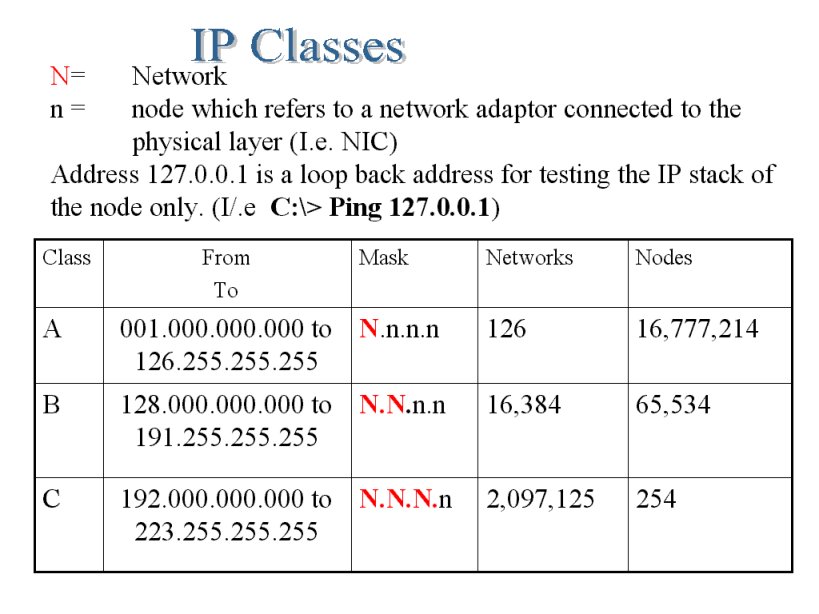
As IP addresses are 32bit there is approx. 4 Billion unique numbers in the decimal range. There had to be a way to manage these numbers as they are certain to run out (as every networkable device in the world needs one). The Internet Assigned Numbers Authority specified classes to distribute the available unique numbers efficiently. This becomes clearer when you understand that an IP address belongs to a block of numbers that represent the LAN, and depending which class of address you are in determines the number of possible nodes (a device on a network) you can have networked.
IP Addresses were grouped into classes, and these determined the maximum number of nodes within the LAN
The Network Mask (also known as a subnet mask or mask) plays a vital role in helping a node to determine if a packet is destined for its network or some other network and needs to be passed out through the gateway device. Below is a binary representation of the 3 standard network masks for Classes A, B and C
Using a method named Network Address Translation, or NAT, groups of similar (private) IP addresses can be contained behind a single globally unique IP address, enabling many computers to use a single global IP connection to the Internet. This global IP address is held by your ISP usually and all their customers are using private 'common' addresses behind the NAT router.
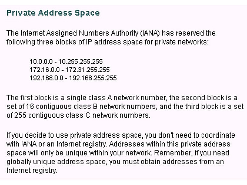
For networks that are not directly connected to the Internet (i.e. not connected at all or behind a NAT router) there are some private addresses reserved in each class.
RFC 1918 was developed for this and states that the following range of numbers are deemed private and must be blocked by networking equipment from leaving the confines of a LAN. Thereby making them private addresses.
Computers use logic to work with binary numbers. Logic is possible because transistors can be configured to perform AND logic operations on these signals. These logic gates as they are known have two inputs and produce 1 output. Below is a Truth table for an AND Logic Gate
Only when both inputs are 1 will the output be 1. This is binary data (a voltage.)
This can be used to compare two binary numbers and determine if they are the same or not. Actually this is exactly what the software drivers for networks cards do every day. They compare the network portion of the IP address of a packet that comes down the wire against network portion of their own configured IP address. If they are the same the packet belongs on this network! see the examples below
First the node must know its own network address
Now the device 'knows' its network address it can compare the IP address of incoming packets to determine if they are on the same network. In the case of a simple networked PC, it will only accept packets for further inspection if they belong to the same network and are addressed to it specifically. In the case of gateways, routers and some switches they can use this to determine if the packet needs routing to a different network.
If a routing device is not on the correct network for the packet, then it will pass the packet to its own configured gateway, which in turn will resolve the packet and make similar decisions until it reaches the correct network destination.
Let us say in the above example that a packet addressed to the class C network address 192.168.36.8 is detected at the network layer.
The networking device (probably a router etc.) has determined its own network from its IP address 192.168.24.8.
Then it compares the incoming IP Packet address 192.168.36.8 to its Network Mask to resolve the network the packet belongs to.
The device then does a direct comparison between its own network and the network of the detected packet.
192.168.24.0 <==> 192.168.36.0 and determines they are different. This packet needs redirecting to a different network, so it would be sent to the gateway configured in its TCP/IP properties. (I.e route the packet)
The network resolution process is an OSI layer 3 operation, and is performed by the network card driver software.
The Network Block
IP addresses are often written with the subnet mask expressed as the number of bits.
I.e. 192.168.16.1/24 the same as 192.168.16.1 with a subnet mask 255.255.255.0 (24 1's)
Other examples 10.0.0.5/8 172.16.67.5/16
The network block is the range of values that represent
- The network address
- all available IP addresses
- and the broadcast address.
There are 4 steps when calculating the network block
- What is the network class?
- Write down the subnet mask
- Resolve the network address (Logic AND)
- Determine the broadcast address (Always the highest number in the network block)
Example using 156.8.200.128/16 - Find the Network Block
It's a Class C IP Address  (>=128 and <192)

156  .    8 . 200. 128
255  . 255.   0  .   0

156  .   8  .  0    .  0          Network address

156  .  8   .  255 . 255      Broadcast address
The network address is not used to configure a machine, nor is the broadcast address. All the values between are suitable for node addresses.
Therefore there will always be two less numbers than the available range for using as IP addresses as every network requires a Network Address and a Broadcast Address.
In a class C network there are 256 possible values, but only 254 addresses can be used as 0 is reserved for the network address and 255 is reserved for the broadcast address.
Exercise Sheet
Ping and Tracert results
Networking Mind Map - Create your own!